 |
|||||||||||||||||||||||
| Home | Site Map | About | News | Purchase | Products | Download | Support | Search | |||||||||||||||
|
|
|||||||||||||||||||||||
 |
|||||||||||||||||||||||
| Home | Site Map | About | News | Purchase | Products | Download | Support | Search | |||||||||||||||
|
|
|||||||||||||||||||||||
Advanced Meshing Topics
The Argus MeshMaker® modules allow you to fully control your mesh shape and size using the intuitive concept of the Mesh Density. The mesh density can be set to any domain outline object (i.e. outline, line feature (river/fault) and point source/sink (i.e. well), and to other zone definition in a density layer that is automatically linked to the mesh layers. In addition, it also takes into consideration many other factors to insure your mesh is valid for a numerical solution.
Argus MeshMaker's auto mesh generation engines analyze the domain outline structure, any internal discontinuities, the mesh density you assign to different domain outline contours and mesh densities you assign to density contours. It then meshes the domain to satisfy your requirements while adhering to the above three prerequisites.
Setting the mesh density to a domain outline is done by specifying the length of an element side. This sets the maximum element side AMG will create.
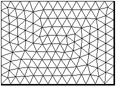
* Click on any image in this page to see it in full size
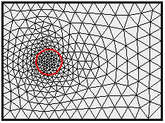
Assigning different mesh density to contours you create in the density layer allow you to set the exact element size within a zone. The mesh on the left was refined by setting the density value of the red contour to value lower than that of the domain outline contour.
 |
 |
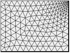
Any contour segment that is smaller than the density specified in the area it is located reduces the mesh density that will be applied. This way the mesh is kept free of acute elements. The domain outline on the right has one small segment at its top right corner. As a result element size is reduced and only gradually grows out to the general density value assigned to the domain.
 |
 |
When domain features are closer to each other than the density applied in the area they are located, the density is reduced. This automatically protect you form having elements where two of their opposite nodes lie on domain boundaries (creating a discontinuity). The domain outline on the right was added two internal discontinuities closer to each other than the general density applied to the domain outline. As a result, element size was automatically reduced.
 |
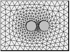 |
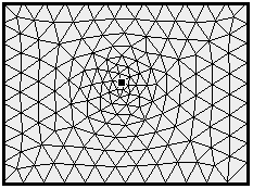
Point objects representing point source/sinks placed in the domain outline force mesh nodes. If placed closer to other point object, or to any other domain features, than the local density, AMG automatically reduces the density.
 |
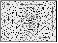 |
Point objects as well as any other domain feature can be assigned a density.
 |
 |
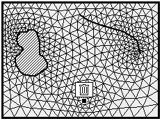
You can place any number and type of domain features in a domain layer and Argus MeshMaker will automatically generate a perfect mesh. Internal discontinuities will be left unmeshed, line features will be meshed such that element sides do not cross them and point objects will force nodes above them. Argus MeshMaker modules enable you to only specify the conceptual physical problem at hand and they will automatically produce the correct mesh. If you need to re-mesh the domain, all relevant information is kept in other layers, so that your mesh can be regenerated in second or minutes.
 |
 |
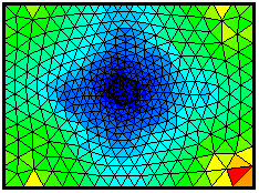
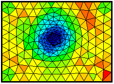
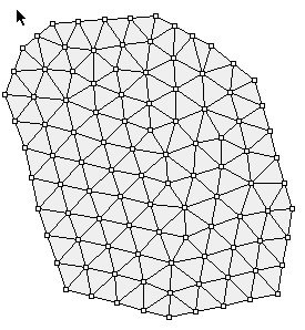
You can control all of the above capabilities, as well as element growth rate, by setting them in the Preferences dialog. The mesh on the left was created by setting element growth rate to minimum, while the one on the right was created by setting element growth rate to maximum.
 |
 |
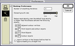
Argus MeshMaker modules allow you full control over every aspect of the automatic mesh generation. You can turn on and off any automatic interpretation performed by the AMG and change every default setting. The following screen-shot presents the mesh preferences control panel.
New Argus MeshMaker modules developed using the Argus ONE PIE technology are offered free fo charge. The two new MeshMaker modules are for creating orthogonal quadrilateral meshes.
A Cartesian Orthogonal Quadrilateral Mesh can be easily created by converting a F.D. grid to a Quad mesh:
Create a grid in Grid layer, the grid can have variable block size or can be rotated, then activate a Quad Mesh
Layer and from the Edit menu select Read Mesh from Grid. Select the Grid Layer from which you want to
copy the Grid.
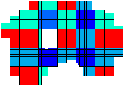
An Orthogonal Quadrilateral Mesh can be easily created using the SuperBlocks PIE.

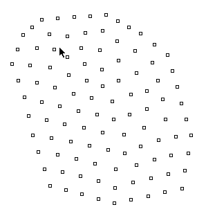
Creating a mesh from a set of X,Y points located in Data type layers.
 |
 |
|
|
|
To find out more about Argus and its products email marketing@argusone.com or call:
+972-9-957-5752
Tech. support: support@argusone.com
snail mail: Argus Holdings, POB 6254, Herzelia, 46160, Israel
Copyright © Argus Holdings, Ltd. 1992-2015